Circuit #7
In modern electronics, this circuit is a differential stage; tubes lovers call it a Long-Tailed Pair. It is used to drive push-pull output stage with two signals in opposite phase and same amplitude.
You may refer to http://www.valvewizard.co.uk/dcltp.html
To use the solver, make sure to understand how to bias it:
- set power supply Vb once for all
- define the DC bias for grids: Vbias; put for instance 50; with cathode resistor, it will determine the quiescent anode currents (you may too put Vbias=0 which means the system is cathode-biased)
- define the offset voltage between grid 1 and 2: dVg (0 for quiescent state); if you put for instance 1, it will mean that Vg1=50+1=51V whilst Vg2 remains at +50V; if you put dVg=-1, then grid of T1 will be at 50-1=49V, the grid of T2 remaining stuck at +50V. This the way to unbalance the stage and see how it impacts anode voltages. You get an evaluation of the gain by putting increasing values, e.g. 10m, 100m, 1, etc. You may find that gain is not symetrical and varies significantly with input offset; tubes are never very linear in open loop!
The solver is sensitive to tube type and cathode resistor. The algorithm should be reworked.
PARAMETERS
Select T1 T2 type
V supply voltage
V fixed bias of T1 and T2 grids
V offset voltage between
T1 and T2 grids
T1 and T2 grids
Ω T1 anode resistor
Ω T2 anode resistor
Ω cathode resistor
SCHEMATICS
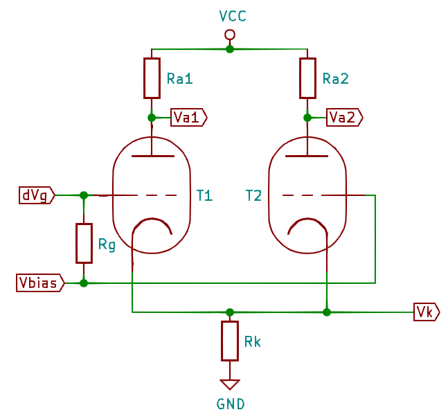
The resistor Rg is just here to remind that T1 and T2 have same DC bias; the input dVg can swing around zero.
The resistor Rg is just here to remind that T1 and T2 have same DC bias; the input dVg can swing around zero.